
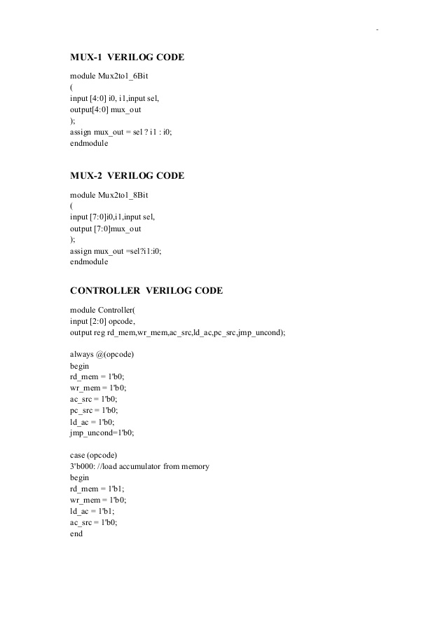
1 MUX followed by the input-output signals. Structural Level Coding with Verilog using MUX exa.

Chipverify
1
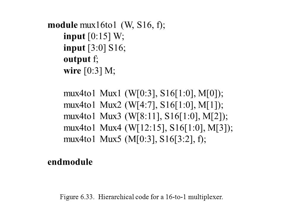
Figure 6 1 A 2 To 1 Multiplexer Ppt Video Online Download
2 words and 6 words but not 4 words and 6 words.
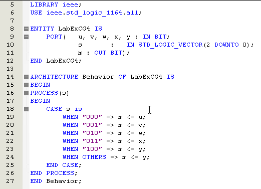
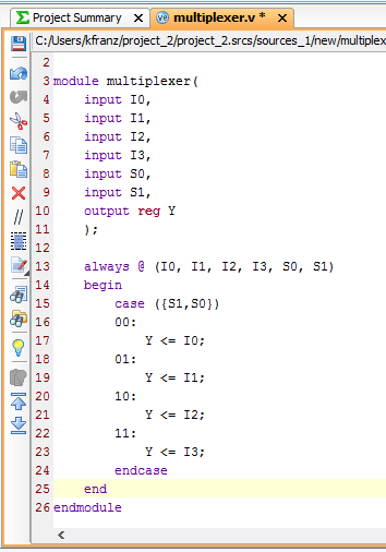
4 to 1 mux verilog code. The case statement checks if the given expression matches one of the other expressions in the list and branches accordingly. Verilog code for a 4-to-1 1-bit MUX using an If statement. 42 Build a circuit from a simulation waveform.
Wait states will be inserted on the wider bus side when necessary. Verilog code for decoder and testbench. A generate block allows to multiply module instances or perform conditional instantiation of any module.
A Verilog case statement starts with the case keyword and. Combinational circuit 1. 4-bit shift register and down counter.
Bit-vector is the only data type in Verilog Z High impedance floating X Unknown logic value 1 Logic one 0 Logic zero Value Meaning An X bit might be a 0 1 Z or in transition. Is this a 3-to-1 multiplexer. Similarly if the MUXF7s are join ed to the MUXF8 then a 161 multiplexer can be.
Truth table of 41 Mux Verilog code for 41 multiplexer using behavioral modeling. If the LUT6s implement 41 multiplexers then the addition of the MUXF7 means that a pair of 81 multiplexers can be fitted into each slice. After synthesizing five of them gave same RTL level circuit in Xilinx Project.
Verilog code for multiplier and. In 1983 VHDL was originally developed at the behest of the US. It is typically used to implement a multiplexer.
Verilog Code for Full Adder using two Half adders. Divide by 3 counter Verilog. To start with the behavioral style of coding we first need to declare the name of the module and its port associativity list which will further contain the input and output variables.
Verilog-2001 is the version of Verilog supported by the majority of commercial EDA software packages. Also explains what is a mux. Code for a Multiplexer in VHDL and Verilog.
Verilog code for 21 MUX using gate-level modeling. Similarly if the x4 is zero and the priority of the next bit x3 is high then irrespective of the values of x2 and x1 we give output corresponding to 3 of x3 - or 011. These statements are particularly convenient when the same operation or module instance needs to be repeated multiple times or if certain code has to be conditionally included based on given Verilog parameters.
Verilog Code for Ripple Carry Adder using Structur. Finding bugs in code. Verilog Code for a 4-to-1 1-bit MUX using a Case statement.
Build a circuit from a simulation waveform. Verilog Code for 14 Demux using Case statements. Verilog Code for 4 bit Comparator.
Verilog code for 4 bit Johnson Counter with. Verilog code for Moore Machine. For the gate level we will first declare the module for 2.
Gray code counter 3-bit Using FSM. The seven-segment display on Basys 3 FPGA will be used to display a 4-digit hexadecimal number which is counting up every 1 second. Verilog - Operators Arithmetic Operators cont I Unary operators I Operators and - can act as unary operators I They indicate the sign of an operand ie -4 negative four 5 positive five.
Verilog code for 2-bit Magnitude Comparator. Module Mux_4_To_1 input 10 i_Select input i_Data1. Verilog code for 4-bit magnitude comparator.
00 sel 01 out 10 a b c 2 3-to-1 MUX 11 input is a dont-care L3. The standard MIL-STD-454N in Requirement 64 in section 451 ASIC documentation in VHDL explicitly requires documentation of Microelectronic Devices in VHDL. The if-else construct may not be suitable if there are many conditions to be checked and would synthesize into a priority encoder instead of a multiplexer.
25 More Verilog Features. Verilog Code for 21 MUX using if statements. The module is a.
Verilog code for a 1-of-8 decoder Verilog code leads to the inference of a 1-of-8 decoder. Verilog code for 4bit comparator. A Multiplexer example There are different ways to design a circuit in Verilog.
One 8-bit lane and eight 8-bit lanes but not one 16-bit lane and one 32-bit lane. In this tutorial I have used seven different ways to implement a 4 to 1 MUX. Negative numbers are represented as 2s compliment numbers.
This VHDL project will present a full VHDL code for seven-segment display on Basys 3 FPGA. A full Verilog code for displaying a counting 4-digit decimal number on the 7-segment display was also provided. Verilog code for Mealy Machine.
Not to be confused with SystemVerilog Verilog 2005 IEEE Standard 1364-2005 consists of minor corrections spec clarifications and a few new language features such as the uwire keyword. 33 Building Larger Circuits. First the bus word widths must be identical eg.
It can be implemented without FSM also. Verilog Code for Digital Clock - Behavioral model. 325 Finite State Machines.
It provides the ability for the design to be built based on Verilog parameters. Second the bus widths must be related by an integer multiple eg. Gray code counter iiUsing Two always block Ex.
Nested conditional operator 41 mux. Department of Defense in order to document the behavior of the ASICs that supplier companies were including in equipment. We follow the same logic as per the table above.
The order of mentioning output and input variables is crucial here the output variable is written first in the bracket then the input ones. 000 001 011 010 110 111 101 100 FSM Design IN VERILOG There are many ways of designing FSMMost efficient are iUsing Three always Block ex. 41 Finding bugs in code.
It will have following sequence of states. Different ways to code Verilog. Verilog code for a 3-to-1 1-bit MUX with a 1-bit latch.
Finding bugs in code. This application note also illustrates VHDL and Verilog code that ensures. 4 to 1 Mux in Verilog.
Patreon NEW The Go Board. Verilog code for 8 bit Binary to BCD using Double Dabble algorithm BCD or Binary-coded decimal is a class of binary encodings of decimal numbers where each decimal digit is represented by four bits. Verilog code for 4 bit mux and test bench.
Let us now write the actual verilog code that implement. Module m21Y D0 D1 S.
8 To 1 Multiplexer Verilog Treewash

Verilog Programming Series 4 To 1 Mux Youtube
What Are Muxes And Demuxes Digilent Blog

Q1 Given The Following Combinational Circuit Use Verilog Hdl On Quartus Tool To 4 To 1 Mux T1 Si So 2 To 1 Mux Output 4 To 1 Mux Si So 1
Verilog Multiplexer Javatpoint

Vhdl Tutorial 14 Design 1 8 Demultiplexer And 8 1 Multiplexer Using Vhdl
5 To 1 Multiplexer Crypto Code

Eprimes Eprimes Page 2